|
The features of a PLC access
network architecture are:
• Bus network topology, meaning
the bandwidth provided by each transformer is shared
by all the users connected to it
• Any electric outlet in the
house will be a communication port as long as it has
a PLC modem, which incorporates two filters to
separate the carrier signals (High-pass Filter) from
the electric current signals (Low-pass Filter).
• There are distance limitations
both for the internal section to the household and
the access section: these are approximately 400
meters for the access section and 50 meters for the
internal section within the home.
• The access controller or PLC
Headend modem is in charge of connecting the various
service networks (Internet, television, telephony)
with the low-voltage line.
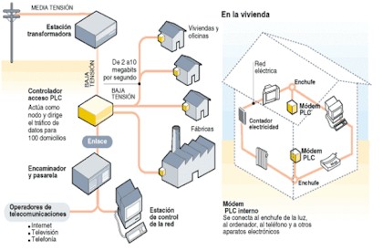
Figure 1. Diagram of a PLC Access
Network. Architecture
PLC technology does not replace,
but rather complements other technologies already
installed in the access section and in the home.
TOPOLOGY OF A PLC NETWORK
Figure 2 shows the general
topology of a PLC network with its three main
components and necessary equipment.
There are three networks involved
in data transmission: the IP or data network, the
distribution or medium-voltage network and the
access or low-voltage network, also called “last
mile”.
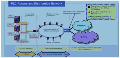
Figure 2. Topology of the PLC
Network
The low-voltage network is used
as an access network for households and industries,
whereas the medium-voltage network acts as a
distribution network, transporting data to the
network backbone. The existence of medium-voltage
PLC technology turns this part of the network into
metro rings, further strengthening PLC as a genuine
broadband alternative and access solution.
The PLC Access Network
The access network is deployed
using low-voltage electrical power lines; it runs
all the way from the transformer in the distribution
center to the electrical outlet in the user’s home.
This network connects the PLC or
CPE (Customer Premises Equipment) modem with the
Head End modem. CPEs are located in the end user’s
home or office, whereas the Head End is in the MV/LV
sub station (or transformer) that is part of the
access network.
Both the HE and the CPE have a
series of elements to filter and separate the
alternating electric current (50 or 60 Hz frequency)
from the high-frequency signals that support video,
data and voice services.
In general, the access network
includes the following:
-
The part located in the user’s
home, which consists of a CPE configured as master
that will be receiving the data signal from the
outside or from a repeater when applicable. These
elements will inject the data signal into the
building’s electrical cabling to provide
connectivity and manage the other existing PLC
devices.
-
The other part that goes from
the master CPE or repeater to the Head End that
serves this coverage area, or, if applicable, to
another repeater that is connected to the Head
End.
Based on the PLC solution used,
as well as on the quality and level of noise of the
low-voltage electrical installation, the distance
between devices ranges between 150 meters and 400
meters with no need for intermediate regenerating
devices. In cases where power lines exceed these
distances, “IR” repeaters (Intermediate Repeaters)
are used, extending the network range.
The PLC Distribution Network
The distribution network is in
charge of connecting multiple networks or scattered
users with the backbone network. In the case of the
PLC networks, the network distribution connects the
Head Ends that serve the low-voltage networks, as
observed in figure 3.
Normally, the design of the
distribution network is a combination of
medium-voltage PLC technology and some of the
technologies typically used in metro rings, such as
SDH and DWDM.
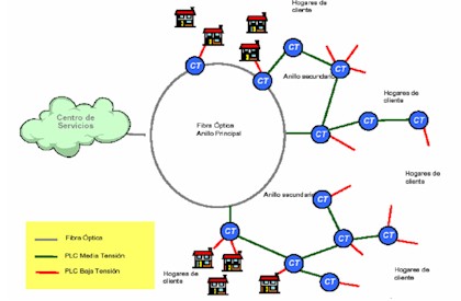
Figure 3. Medium-voltage and Fiber
Optics PLC distribution network
PLC offers an alternative to
current metropolitan rings by enabling the use of
the medium-voltage network for data transmission.
This is an advantage in places where, due to low
customer density, it is not profitable to deploy
fiber optics to low-voltage transformers.
The medium-voltage PLC solution
has as main advantages:
The technology used in
medium-voltage equipment is essentially the same one
used in low-voltage equipment, only customized in
order to improve its performance, reliability, and
latency.
The medium-voltage node can
perform different functions depending on its
position in the network. It can thus act as Head End
or heading, repeater or terminal equipment for the
medium-voltage network, with or without derivations
to the low-voltage network while acting as Head End
equipment for it.
Josefina Cano
Rapporteur
Group on Network Infrastructure |