
Page 111 - GuideFWA
P. 111
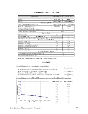
IN TER FER EN C E AN ALYSIS C ASE

                                            Param eter                 Interfering TX                   Victim R X

                    System                                                           PC S1900                 PHS
                    D evice                                                       B ase Station         B ase Station
                                                        Frequency D ata

                    1850-1990 M H z Frequency Block                    A (upperpart) 1910 -1930 M H z
                    W orking Frequency (M H z)
                    N um berofguard channels                                       1930,200             1929,350
                    G uard Band betw een channeledges (KH z)
                    TX/R X frequency O ffset(KH z)                                          00

                                                                                                 600

                                                                                                 850,0

                                                        System D ata

                    TX Pow er(dBm )                                                46

                    R X sensitivity (dBm )  **See N ote **                                              -78
                                                                                                        12
                    Specific C /Ivalue forR eceiverVictim System (dB)

                                                        Antenna and FeederD ata

                    Antenna heigth (m )                                            25,0                 15,0
                    Antenna G ain (dBi)                                            17,0                 10,0
                    Antenna H orizontalBeam w idth (º)                             105                  om ni
                    Antenna VerticalBeam w idth (º)
                    Antenna D ow ntilt(º)                                            9                    8
                                                                                    -3                   -7

                    FeederLosses (dB)                                              2,0 1,0

                                                        O therC alculation Inputs

                    Im provem enton TX m ask specification (dB)                                  0,0
                    Allow ed R x D esensitization (dB)                                           1,0

                    N ote:This is the R eceiverSensitivity w ith R ayleigh Fading (10 dB )

                                                        R ESU LTS

R equired distances forD esentization equalto 1 dB :                                                  R eq.distance (m )

     W hen both TX and R X are on R X and TX antenna 3dB-beam w idth                                          2,1
     W hen only R X is on TX antenna 3dB-beam w idth                                                  notapplicable
     W hen only TX is on R X antenna 3dB-beam w idth
     W hen both TX and R X are outofR X and TX antenna 3dB-beam w idth                                        0,1
                                                                                                      notapplicable

R equired distances w hen TX and R X antennae are on-beam ,fordifferentD esentization:

Desentization (dB)3,00                                                 D esentization (dB )           R eq.D istance (m )  ###
                  2,50                                                                                                     ###
                  2,00       50,0 100,0 150,0 200,0 250,0 300,0 350,0             1,0                           2,1        ###
                  1,50                      Required Distance (m)                                                          ###
                  1,00                                                        0,25                          328,8          ###
                  0,50                                                        0,50                          184,1          ###
                  0,00                                                        0,75                                         ###
                                                                              1,00                            2,5          ###
                        0,0                                                   1,25                            2,1          ###
                                                                              1,50                            1,9          ###
                                                                              1,75                            1,7
                                                                              2,00                            1,5
                                                                              2,25                            1,4
                                                                              2,50                            1,3
                                                                              2,75                            1,2
                                                                              3,00                            1,1
                                                                                                              1,1

Inter-American Telecommunication Commission                                                                                97