
Page 16 - GuideFWA
P. 16
2.1.2. Formulae and Variable Description
The following agreed variables have been defined to be used in calculations.
By convention, terms are presented in two ways: without any prime symbol ’ it represents analog
value (e.g. watts or power ratios) and with a prime symbol ’ it represents the logarithmic
equivalence (e.g. dB, or dBm)
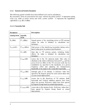
2.1.2.1 Transmitter Path
Parameter Description
Analog form logarith. Launch power of the interfering device at TX antenna
form output. Its value is obtained by calculation (see
formulae)
PL (Mw) P’L (dBm)
Peak power of the interfering transmitter during active
Pmax (mW) P’max (dBm) burst (value given in systems specifications)
G’tx (dB)
Gain due to TX antenna system, including feeder
L’mask (dB) effects. Its value is obtained by calculation (see
formulae)
G’txant (dBi)
L’txant (dB) Losses due to the TX emission mask. This value is
L’txfeeder (dB) obtained as the relative difference between P’max and the
power level (in dBm) of the TX emission mask due to
modulation (as specified in the standards), at a given
frequency offset and adjusting the measurement
bandwidth of the mask to the victim RX bandwidth.
Isotropic gain of TX antenna. A reference value was
agreed by the Experts group for each system taken into
account actual deployments
Losses due to the directivity of TX antenna. Both
horizontal and Vertical radiation patterns have been
taken into account. Reference values have been agreed
by Experts Group based on actual deployments.
Losses due to the antenna feeder. Reference values have
been agreed by Experts Group based on actual
deployments.
6