
Page 17 - GuideFWA
P. 17
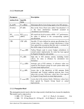
2.1.2.2 Receiver path

Parameter    logarith.          Description
analog form  form
                                Maximum allowed interfering signal at the RX antenna.
PR (mW)      P’R (dBm)
D (ratio)                       Rise in the Noise Floor (also called “desentization”). It
             D’ (dB)            is the basic interference threshold assumed in
                                calculations (see formulae)
RX sensitivity RX’sensitivity
                                RX sensitivity level to assure a BER < 10-3 performance.
(mW)         (dBm)              Its value is defined in the corresponding systems
                                specifications
CIR CIR’ (dB)
                                Specific C/I ratio defined in system specifications for a
             F’margin (dB)      system alone (i.e. without external interference). It has
             G’rx (dB)          been agreed the assumption that this ratio is constant for
             G’rxant (dBi)      the whole range of received useful signal.
             L’rxant (dB)
                                Fading Margin used in power budget calculations in
             L’rxfeeder (dB)    normal system deployments. Its value has been agreed
                                by Experts Group for each system

                                Gain due to RX antenna system, including feeder
                                effects. Its value is obtained by calculation (see
                                formulae)

                                Isotropic gain of RX antenna. A reference value was
                                agreed by the Experts group for each system taken into
                                account actual deployments

                                Losses due to the directivity of RX antenna. Both
                                horizontal and Vertical radiation patterns have been
                                taken into account. Reference values have been agreed
                                by Experts Group based on actual deployments.

                                Losses due to the antenna feeder. Reference values have
                                been agreed by Experts Group based on actual
                                deployments.

2.1.2.3 Propagation Model

The propagation model used, is the two-slope model, which has been chosen for simplicity.

This model can be expressed as:

      L’(dB) = 38 + 20 log (d)               , for 1< d < 4htxhrx/? (in meters)             (1a)

      L’(dB) = 38 - 20 log (4htxhrx/?) + 40 log (d) , for d= 4htxhrx/? (in meters)(1b)

Inter-American Telecommunication Commission                                                       7