
Page 252 - GuideFWA
P. 252
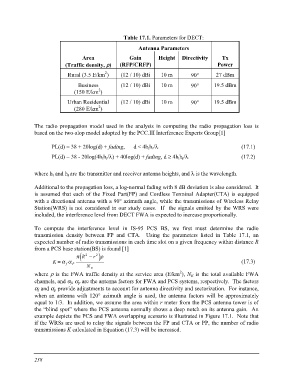
Table 17.1. Parameters for DECT:

                                          Antenna Parameters

             Area                         Gain  Height Directivity Tx
     (Traffic density, ?)
      Rural (3.5 E/km2)        (RFP/CRFP)                          Power

           Business            (12 / 10) dBi 10 m                  90° 27 dBm
         (150 E/km2)
                               (12 / 10) dBi 10 m                  90° 19.5 dBm
      Urban Residential
         (280 E/km2)           (12 / 10) dBi 10 m                  90° 19.5 dBm

The radio propagation model used in the analysis in computing the radio propagation loss is
based on the two-slop model adopted by the PCC.III Interference Experts Group[1]

     PL(d) = 38 + 20log(d) + fading, d < 4hthr/?                                 (17.1)
     PL(d) = 38 - 20log(4hthr/?) + 40log(d) + fading, d = 4hthr/?                (17.2)

where ht and hr are the transmitter and receiver antenna heights, and ? is the wavelength.

Additional to the propagation loss, a log-normal fading with 8 dB deviation is also considered. It
is assumed that each of the Fixed Part(FP) and Cordless Terminal Adapter(CTA) is equipped
with a directional antenna with a 90° azimuth angle, while the transmissions of Wireless Relay
Station(WRS) is not considered in our study cases. If the signals emitted by the WRS were
included, the interference level from DECT FWA is expected to increase proportionally.

To compute the interference level in IS-95 PCS BS, we first must determine the radio

transmission density between FP and CTA. Using the parameters listed in Table 17.1, an

expected number of radio transmissions in each time slot on a given frequency within distance R

from a PCS base station(BS) is found [1]

     K =afaP  ( )p R2 - r 2 ?                                                    (17.3)

              NE

where ? is the FWA traffic density at the service area (E/km2), NE is the total available FWA

channels, and af, ap are the antenna factors for FWA and PCS systems, respectively. The factors

af and ap provide adjustments to account for antenna directivity and sectorization. For instance,

when an antenna with 120° azimuth angle is used, the antenna factors will be approximately

equal to 1/3. In addition, we assume the area within r meter from the PCS antenna tower is of

the “blind spot” where the PCS antenna normally shows a deep notch on its antenna gain. An

example depicts the PCS and FWA overlapping scenario is illustrated in Figure 17.1. Note that

if the WRSs are used to relay the signals between the FP and CTA or PP, the number of radio

transmissions K calculated in Equation (17.3) will be increased.

238