
Page 227 - GuideFWA
P. 227
99
Distribution of interference
90 on arbitrary channel (rmin=100m)
70 Distribution of interference on
least-interfered channel
Pr{I < x}
(percent) 50
30 Assumptions:
FWA traffic density = 300 E/km2
Downlink interference only
10 FWA "macrobase" stations with 12 dBi gain
six overlapping 90-degree sectors per base
120 FWA channels
15 dB building attenuation
Cochannel interference only
1
-70 -65 -60 -55 -50 -45
x (dBm)
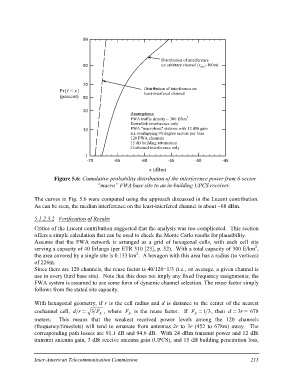
Figure 5.6: Cumulative probability distribution of the interference power from 6-sector
“macro” FWA base site to an in-building UPCS receiver.
The curves in Fig. 5.6 were computed using the approach discussed in the Lucent contribution.
As can be seen, the median interference on the least-interfered channel is about -68 dBm.
5.1.2.3.2 Verification of Results
Critics of the Lucent contribution suggested that the analysis was too complicated. This section
offers a simple calculation that can be used to check the Monte Carlo results for plausibility.
Assume that the FWA network is arranged as a grid of hexagonal cells, with each cell site
serving a capacity of 40 Erlangs (per ETR 310 [23], p. 52). With a total capacity of 300 E/km2,
the area covered by a single site is 0.133 km2. A hexagon with this area has a radius (to vertices)
of 226m.
Since there are 120 channels, the reuse factor is 40/120=1/3 (i.e., on average, a given channel is
use in every third base site). Note that this does not imply any fixed frequency assignments; the
FWA system is assumed to use some form of dynamic channel selection. The reuse factor simply
follows from the stated site capacity.
With hexagonal geometry, if r is the cell radius and d is distance to the center of the nearest
cochannel cell, d r = 3 FR , where FR is the reuse factor. If FR = 1 3, then d = 3r = 678
meters. This means that the weakest received power levels among the 120 channels
(frequency/timeslots) will tend to emanate from antennas 2r to 3r (452 to 678m) away. The
corresponding path losses are 91.1 dB and 94.6 dB. With 24 dBm transmit power and 12 dBi
transmit antenna gain, 3 dBi receive antenna gain (UPCS), and 15 dB building penetration loss,
Inter-American Telecommunication Commission 213