
Page 223 - GuideFWA
P. 223
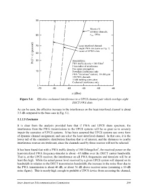
Pr{I < x} (percent)    99

                                                                                             Worst of 8
                                                                                             arbitrary channels,
                       90 rmin=100m

                       70 Least-interfered channel:
                                                                               single FWA slot (same as Fig. 1)
                                                                               worst of 8 FWA slots

                       50

                       30 Assumptions:
                                                                      FWA traffic density = 300 E/km2
                                                                      5-km radius of interference
                                                                      Free space propagation

                       10 Downlink interference only
                                                                      FWA "microbase" stations, 10 dBi gain
                                                                      120 FWA channels
                                                                      15 dB building attenuation
                                                                      Cochannel interference only

                         1
                          -70 -65 -60 -55 -50 -45

                                                         x (dBm)

  Figure 5.4: Effective cochannel interference to a UPCS channel pair which overlaps eight
                                                         DECT FWA slots.

As can be seen, the effective increase in the interference on the least-interfered channel is about
3.5 dB compared to the base case in Fig. 5.1.

5.1.1.5 Conclusion

It is clear from the analysis provided here that if FWA and UPCS share spectrum, the
interference from the FWA transmissions to the UPCS systems will be so great as to severely
impair the operation of UPCS systems. It has been assumed that UPCS systems use some form
of dynamic channel assignment, and can select the least-interfered channel. In that case, it is the
lower tail of the cumulative distribution function that is of interest, and the distances to nearby
interference sources are irrelevant, since the channels used by those sources will not be selected.

It has been found that with a FWA traffic density of 300 Erlangs/km2, the received power on the
least-interfered FWA frequency-timeslot is about -65.6dBm over the DECT carrier bandwidth.
That is, at the UPCS receiver, the interference on all FWA frequencies and timeslots will be at
least this high. While the actual power level received by a given UPCS system will depend on its
bandwidth in relation to the DECT transmission bandwidth, the increase in the noise floor due to
the FWA transmission is about 46 dB, or about 36 dB above receiver noise (assuming a 10-dB
noise figure). This is nearly high enough to prohibit a UPCS device from accessing the channel,

Inter-American Telecommunication Commission  209